News
Insights into Laue Cameras and Single Crystal Orientation
29th Jul, 2021
Laue cameras are a core part of the Photonic Science product offering. This article looks at the working principles of diffraction Laue cameras and to give some insight into what makes our Laue crystal orientation systems so special.
Laue diffraction is an extremely valuable tool for investigating the structure and orientation of a single-crystal material. This method can be used to quantify how much a crystal’s actual growth direction has deviated from the intended growth direction. This information can be used for quality control or for reorienting the crystal for subsequent cutting. In addition, users can evaluate whether the sample is a true single crystal, quantify the misorientation of imperfections, and detect changes in orientation throughout the bulk crystal by mapping across a crystal face.
Because of their unique properties, single-crystal materials often play an important role in creating novel products such as lasers and turbine blades. Single crystals are particularly interesting to examine because they contain no grain boundaries, making their electrical, physical, and thermal properties distinct from polycrystalline materials.
Start with the basics; give us a brief introduction to Laue tool
Typically, the Laue technique uses what we call a back reflection geometry. We have a polychromatic low energy ( 50keV) X-ray beam going through a detector and a sample on the other side of the detector, reflecting the X-ray beam , forming set of diffraction spots which are recorded directly onto the detector. The indexation of the diffraction pattern is specific for each crystal orientation and allows materials scientists and physicists growing and then cutting crystals with electro optical properties
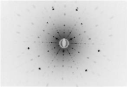
Laue Spots Sapphire Sample C-axis aligned
What actually is Laue diffraction?
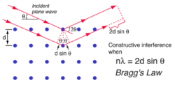
If we dig down a little bit into the physics of Laue cameras, what we have are X-rays interacting with electron clouds on a single crystal or an alloy. The reflected beam is recorded onto the Laue detector if it satisfies Bragg’s law. It’s a relatively simple equation, which allows you to locate the spots according to a specific orientation of a crystal.
(Braggs Law :When the incident angle of the X-ray beam is such that difference in X-ray path lengths between crystal planes is an integer number of wavelengths, constructive interference occurs, creating a diffracted beam).
How do you acquire a Laue diffraction pattern?
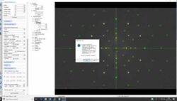
PSEL dedicated Laue software
Let’s say I want to measure a mis-cut angle from a crystallographic orientation down to <0.1 degree accuracy; you would overlay a theoretical pattern onto an experimental one and record the deviation from the theoretical spot position. The Bragg equation will enable us to derive the exact misoriention over three angular axis of the crystal lattice using our dedicated Laue software.
So, what are the components in a Laue system? PDF Laue Brochure
We provide a high brightness micro focus X-ray source, a low noise large area X-ray detector, and a manual or motorized stage on to which the sample is positioned. People in the past have used two kilowatt X-ray sources in their Laue cameras, which required complex cooling and power hungry installations whereas we are using 25W of effective power.
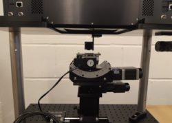
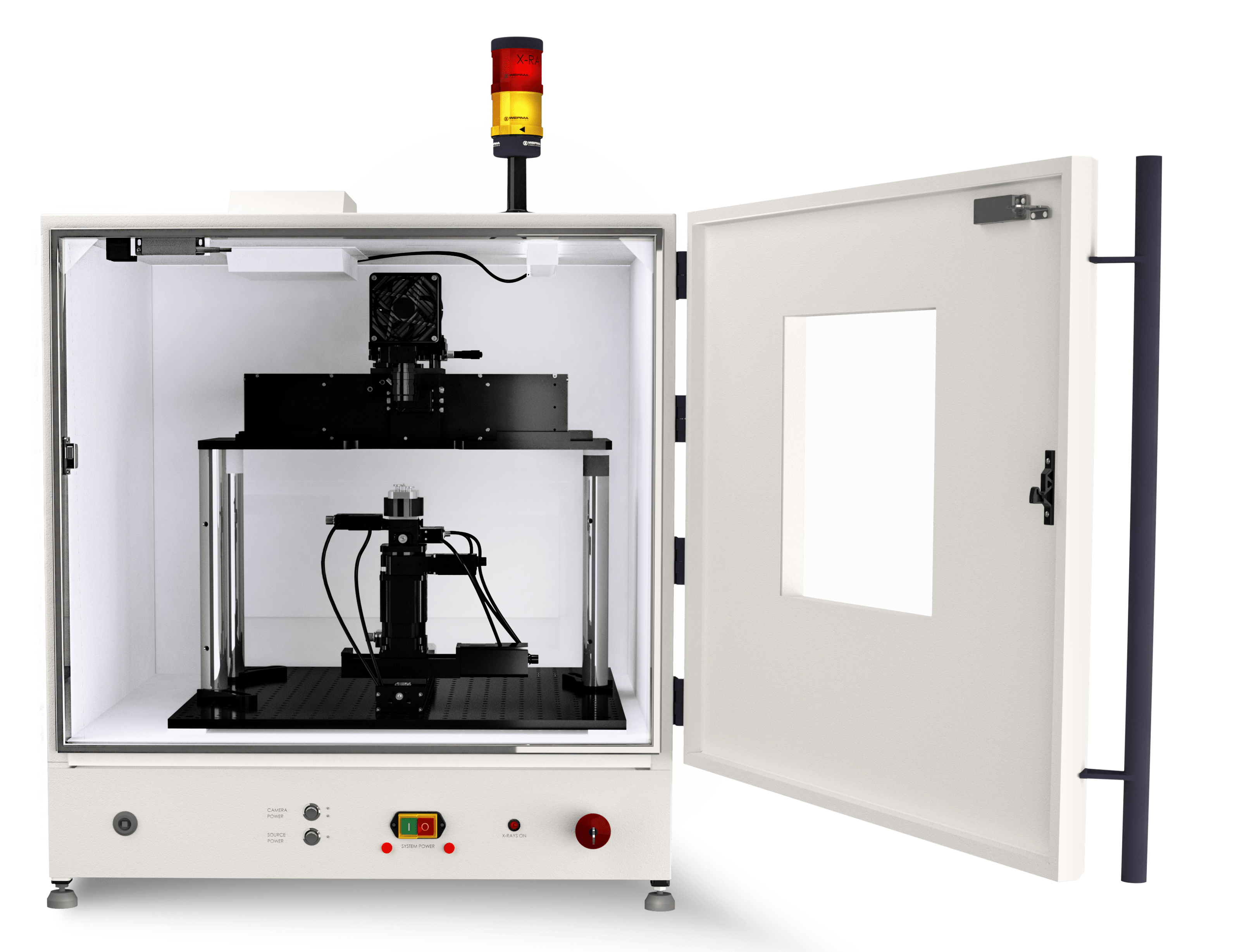
Vertical Laue system
Can you talk a bit about our Laue system?
Thanks to a much smaller X-ray beam footprint delivered onto the sample, the system can handle sub millimetre range samples. Combined with a large area, high resolution detector we can achieve orientation accuracy down to 0.05 degree. The system geometry can accommodate wafers, large ingots as well as larger components such as turbine alloys.
How else do our Laue cameras differ from other systems on the market?
As the X-ray beam footprint is a lot smaller, we can help material scientists and physicists identify sub grain structures / orientation. The system can acquire up to 10,000 orientation measurements automatically on large polycrystalline samples such as solar cells, helps to understand the effect of grain orientation versus cell efficiency.
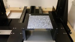
Polycrystalline Silicone Wafer Scanner
It comes with a range of accessories too, why might you consider these?
Our systems can be customized according to the customer’s environment and requirements. We usually provide a turn-key solution, sample holders, goniometers, scanning stages to align crystals on a routinely basis prior to transfer to a suitable cutting tool.
Detector materials such CdTe, GaAs, microelectronic substrates such GaN, piezo materials cut and diced as wafers are subject to automatic batch testing. We will have sample holders hosting up to 100 samples which will be scanned using a single press button procedure.
Laser materials, or Sapphire come in large bulk, heavy duty stages are then used to accommodate sample from 10 up to >100kg.
Thin film orientation such as AlN are also controlled, using the finest precision stages with multi point scanning routine.
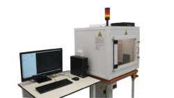
Laue Crystal Orientation System
Is there anything else you would like to add?
In the beginning, we started selling these systems and cameras for scientific purposes, We are now selling these more for industrial applications. They’re built to purpose, unlike old-fashioned expensive diffraction systems.
We have over 200 systems in the field in operation right now.
If you have enjoyed this question and answer session, and would like more information about our Laue cameras, simply contact a member of the Photonics Science team today.